PythonでGeoSpatial Dataの測地系と投影法の変更_1[Chapter 11]
PythonでGeoSpatial Dataの読み書きについて_3[Chapter 10] に引き続き、GeoSpatial Dataの測地系と投影法の変更の基本を学んでおきます。
本tutorialは、Python Geospatial Developmentを参考にして、実践的に使えるPythonでGeoSpatialの使い方を学んでいくものです。
また、本Blog中のsource code等に関しては、あくまでも参考としてください。なにがあっても責任とれませんので。
そこんところ、ヨロシク~~!!
準備
PythonでGeoSpatial Dataの読み書きについて_1[Chapter 8] でPythonとGeoSpatialに関するlibraryが設定できているもとして進めていきます。
UTM座標の投影法の変換
GISのデータは多くの測地系や投影法があり、いつも自分の使いたい座標系ではないことが多いですが、この測地系と投影法の座標変換を学んでおくことは非常に有用です。
ここでは、UTM座標系をWGS84の経度緯度座標系に変換する例を学びます。
UTM Shapefile data download
WebGISのwebsiteからUSAのマイアミのUTM座標系のをmiami Shapefile をdownloadします。
そして、miami.zipを解凍してF:¥shapefile_data¥miami folderに解凍したfileをcopyします。
copyするfileは
-
miami.shp
-
miami.shx
-
miami.dbf
-
miami_datum_reference.txt
の4つのfileです。
投影法の変換 code
とりあえず、Ediorで下記のcodeを入力して、保存します。
保存先はf:¥python_example¥chapter_5¥ folderにchangeProjection.pyで保存します。
[python]
import os, os.path, shutil
from osgeo import ogr
from osgeo import osr
# Define the source and destination projections, and a
# transformation object to convert from one to the other.
srcProjection = osr.SpatialReference()
srcProjection.SetUTM(17)
dstProjection = osr.SpatialReference()
dstProjection.SetWellKnownGeogCS(‘WGS84′) # Lat/long.
transform = osr.CoordinateTransformation(srcProjection, dstProjection)
# Open the source shapefile.
inPath = "f:¥¥shapefile_data¥¥miami"
srcFile = ogr.Open(inPath +"¥¥" +"miami.shp")
srcLayer = srcFile.GetLayer(0)
# Create the dest shapefile, and give it the new projection.
outPath = "f:¥¥shapefile_data¥¥miami-reprojected"
if os.path.exists(outPath):
shutil.rmtree(outPath)
os.mkdir(outPath)
driver = ogr.GetDriverByName("ESRI Shapefile")
dstPath = os.path.join(outPath, "miami.shp")
dstFile = driver.CreateDataSource(dstPath)
dstLayer = dstFile.CreateLayer("layer", dstProjection)
# Reproject each feature in turn.
for i in range(srcLayer.GetFeatureCount()):
feature = srcLayer.GetFeature(i)
geometry = feature.GetGeometryRef()
newGeometry = geometry.Clone()
newGeometry.Transform(transform)
feature = ogr.Feature(dstLayer.GetLayerDefn())
feature.SetGeometry(newGeometry)
dstLayer.CreateFeature(feature)
feature.Destroy()
# All done.
srcFile.Destroy()
dstFile.Destroy()
[/python]
注意)上記codeで¥は全角ですので、半角にするかもしくは、バックスラッシュに置き換えてください。
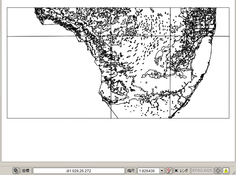
PyScriptでrunすると、何も起こりませんが、f:¥shapefile_data¥miami-reprojectedのfolderが作成されて、投影法がWGS84に変換されたfileができあがります。
作成されたfileは
-
miami.shp
-
miami.shx
-
miami.dbf
-
miami.prj (projection定義)
の4つのfileです。
な感じでWGS84のprjが作成されていることが確認できます。
codeの説明
changeProjection.pyが何を行っているのかを順にみていきましょう。
1.library 読み込み
import os, os.path, shutil from osgeo import ogr from osgeo import osr
2.入出力Shapefileのprojection定義
# Define the source and destination projections, and a
# transformation object to convert from one to the other.

srcProjection = osr.SpatialReference()
srcProjection.SetUTM(17)

dstProjection = osr.SpatialReference()
dstProjection.SetWellKnownGeogCS('WGS84') # Lat/long.

transform = osr.CoordinateTransformation(srcProjection, dstProjection)
入力ShapefileのprojectionをsrcProjectionで定義します。そしてSetUTM(17)でUTM17系とします。
出力ShapefileのdstProjectionをsrcProjectionで定義します。そしてSetWellKnownGeogCS('WGS84')で世界測地系とします。
transformでCoordinateTransformationを定義します。
3.入力Shapefileのopen
# Open the source shapefile.

inPath = "f:¥¥shapefile_data¥¥miami"
srcFile = ogr.Open(inPath +"¥¥" +"miami.shp")
srcLayer = srcFile.GetLayer(0)
4.出力先folderの作成
# Create the dest shapefile, and give it the new projection.

outPath = "f:¥¥shapefile_data¥¥miami-reprojected"
if os.path.exists(outPath):
    shutil.rmtree(outPath)
os.mkdir(outPath)
5.出力Shapefileの作成
driver = ogr.GetDriverByName("ESRI Shapefile")
dstPath = os.path.join(outPath, "miami.shp")
dstFile = driver.CreateDataSource(dstPath)
dstLayer = dstFile.CreateLayer("layer", dstProjection)
詳細については、PythonでGeoSpatial Dataの読み書き_2[Chapter 9] を参考にして下さい。
6.Projectionの変換
# Reproject each feature in turn.

for i in range(srcLayer.GetFeatureCount()):
    feature = srcLayer.GetFeature(i)
    geometry = feature.GetGeometryRef()

    newGeometry = geometry.Clone()
    newGeometry.Transform(transform)

    feature = ogr.Feature(dstLayer.GetLayerDefn())
    feature.SetGeometry(newGeometry)
    dstLayer.CreateFeature(feature)
    feature.Destroy()
srcLayerのfeature数でloopします。
featureとgeometryに入力Shapefileの情報をcopyして、newGeometryのcloneを作成して、Transform(transform)で投影法の変換を行います。
属性値については変更はありませんので、そのまま出力Shapefileに追加していきます。
feature.SetGeometryで変換後のgeomertyを追加して、dstLayerに新しくfeatureを作成して追加していきます。
7.Objectの破棄
# All done.

srcFile.Destroy()
dstFile.Destroy()
の感じで投影変換されていることが確認できます。
順番にみていくと理解できると思います。
objectの引数が不明な場合は、PyScriptのインタプリタでhelp(osr)などを入力すると、使用方法がインタプリタ画面に出力されます。
今回のまとめ
今回は、PythonでのGeoSpatial dataのShapefileの投影法変換を行いました。
ExercisesでJGD2000の投影法を使って、Shapefileの変換をtyrしてください。
次回は、測地系の変換をやってみます。
また、本tutorialは、Python Scriptの基本的なことはある程度理解している前提で今後も話を進めていきます。また、誤字、脱字、spell間違いや勘違いや翻訳間違いなど多々出てくると考えられます。
それは違うじゃん!!とかいろんな意見をいただければと思います。
そこんところ ヨロシク~~!!


Comments are closed.